best_model.pt (RML2016.10a, 93.36 % accuracy at +18 dB)xc7s50csga324-1 · Vitis HLS 2026.1 · clock 10 ns (100 MHz)MRT_FrontEnd_GuideArch\
├── 00_ROADMAP.html / .md ← this document (open the .html in a browser)
├── 01_guide_notes\ ← the 3 pages of the guide's hand-drawn architecture
├── 02_results\ ← function sheet + check sheets (Excel) + fold proof
├── S1_input_rom_raw_src\ ← Step 1 Input ROM (I, Q)
├── S2_s2p\ ← Step 2 S2P1 / S2P2 shift registers
├── S4_patch_embed_src\ ← Step 3+4 ROM-W' + matrix-vector multiplier
├── S5_token_pos_src\ ← Step 5+6 Token ROM + MUX + RAM-E + ROM-P' + adder
└── S7_front_end_src\ ← Step 7 complete front end (all blocks, one top level)
Every S.. folder is one Vitis HLS component source: hls_config.cfg, src\ (hardware C++),
tb\ (testbench), data\ (ROM contents + reference values) and a README.txt.
01_guide_notes)| Guide page | What the guide drew |
|---|---|
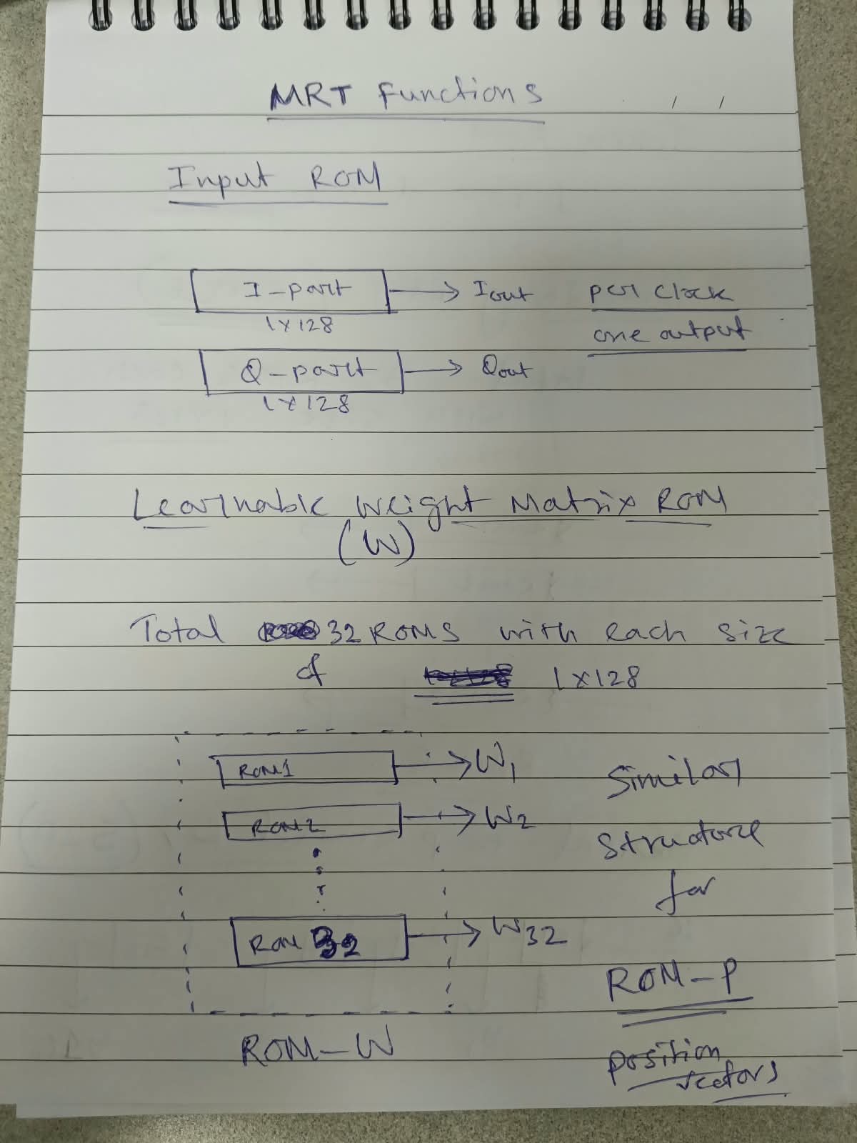
| Page 1 – "MRT functions" | Input ROM: I-part 1×128 → I_out, Q-part 1×128 → Q_out, per clock one output. Learnable weight matrix ROM (W): 32 ROMs, each 1×128 (ROM1 → W1 … ROM32 → W32) = ROM-W. "Similar structure for ROM-P (position vectors)". |
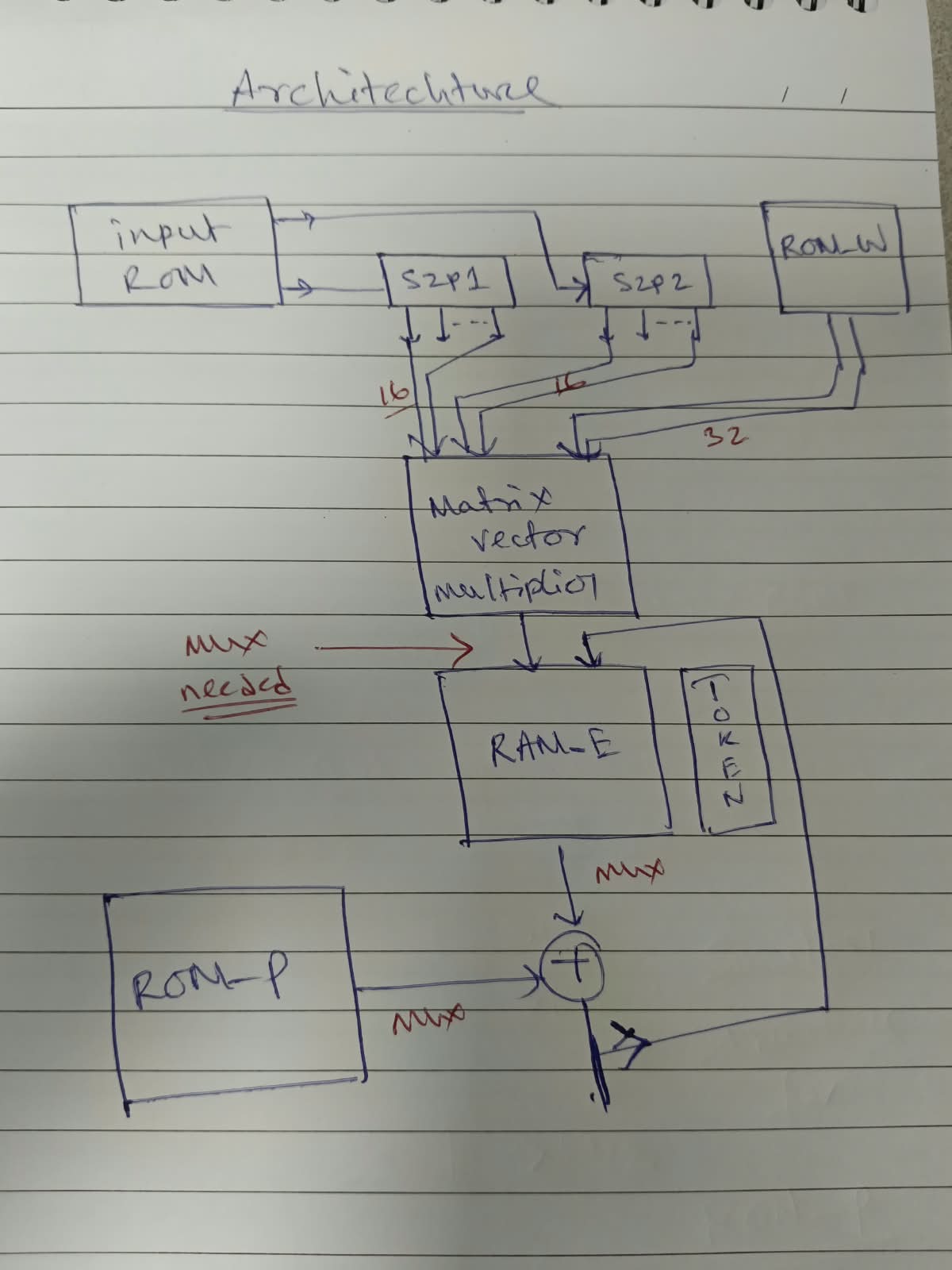
| Page 2 – "Architecture" | Input ROM → S2P1 (I) and S2P2 (Q) → 16 + 16 values → Matrix-vector multiplier ← 32 weights from ROM-W → MUX ("mux needed") → RAM-E with TOKEN → RAM-E → MUX → adder (+) ← MUX ← ROM-P → write back into RAM-E. |
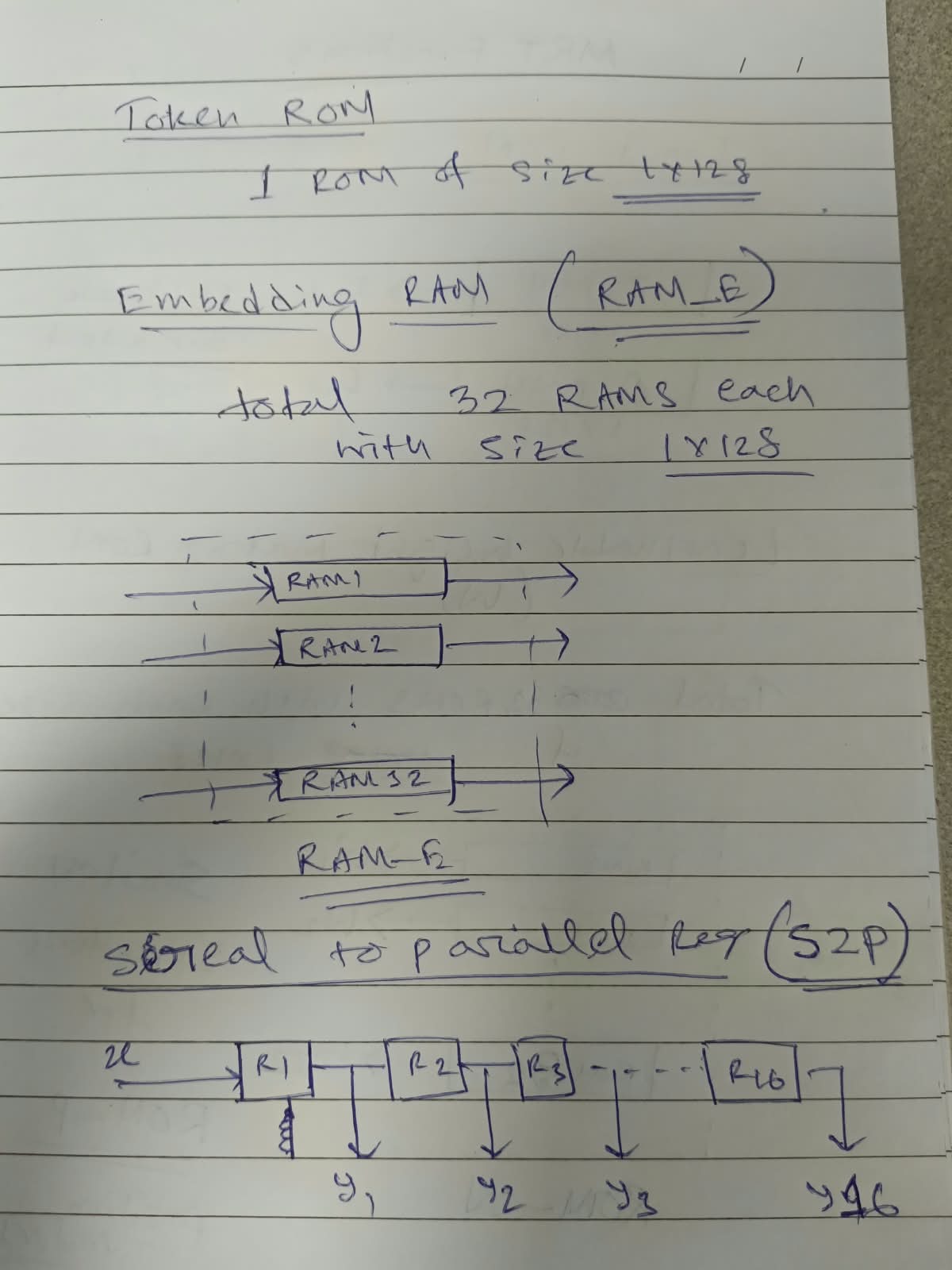
| Page 3 | Token ROM: 1 ROM of size 1×128. Embedding RAM (RAM_E): "32 RAMs each 1×128". Serial-to-parallel register (S2P): x → R1 → R2 → R3 … → R16, outputs y1 … y16. |
 ① Input ROM ──I──► ② S2P1 (R1..R16) ──16──┐
   (1x128 each) ─Q──► ② S2P2 (R1..R16) ──16──┼──► ④ Matrix-vector multiplier ──► ⑤ MUX ──► RAM-E (9 x 128)
                                             │        (32 multiplies + sum)           ▲           │
                 ③ ROM-W' (32 ROMs) ───32────┘                                   TOKEN ROM        ▼
                                                                                    ⑥ adder (+) ◄── ROM-P'
                                                                                        │
                                                                    ⑦ write back ◄──────┘ ──► to Encoder 0
| Order | Guide block | Function (function sheet) | Our step | Folder | HLS top |
|---|---|---|---|---|---|
| 0 | (not drawn) | (raw − channel_mean) / channel_std | removed – folded into ROM-W′ and ROM-P′ | S1_input_rom_raw_src\rom_data |
– |
| ① | Input ROM (I, Q 1×128, 1 output per clock) | input (raw signal 2×128) | Step 1 | S1_input_rom_raw_src |
input_rom |
| ② | S2P1 + S2P2 (R1…R16, y1…y16) | extract_patches (2,128) → (8,32) | Step 2 | S2_s2p |
s2p |
| ①→② | wiring Input ROM → S2P | – | Step 3 (wiring only, done in Step 7) | – | – |
| ③④ | ROM-W (32 ROMs 1×128) + matrix-vector multiplier | patch_embedding → linear (8,32) → (8,128) | Step 4 | S4_patch_embed_src |
patch_embed |
| ⑤ | Token ROM + MUX → RAM-E | add_token_and_positions (part 1) | Step 5 | S5_token_pos_src |
token_pos |
| ⑥⑦ | ROM-P + adder + write back | add_token_and_positions (8,128) → (9,128) | Step 6 (same block as 5) | S5_token_pos_src |
token_pos |
| all | the complete drawing on page 2 | functions 1–3 together | Step 7 | S7_front_end_src |
mrt_front |
| Sketch | Our design | Reason |
|---|---|---|
| No normalization block | (x − mean)/std removed, merged into ROM-W′ = W/std and ROM-P′ |
raw data in the ROM, no retraining, mathematically identical (proof: max error 6.7e-07) |
| No bias ROM | patch bias b′ added into ROM-P′ rows 1–8 | nn.Linear(32→128) has a bias; this keeps the drawing unchanged |
| RAM-E "32 RAMs × 1×128" | RAM-E = 9 × 128 (token + 8 patches) | the output of add_token_and_positions is (9,128) |
| ROM-P "similar structure" | ROM-P′ = 9 × 128 | one position vector per token |
| no control drawn | HLS generates the counters, MUX selects and handshakes | from the C++ loops |
| no hold register | patch held for its 128 multiplier clocks (x[32] in Step 4) |
S2P fills every 16 clocks, multiplier needs 128 clocks per patch |
norm_stats.npz: mean I = 7.121e-05, mean Q = −6.219e-04, std I = 0.00581268, std Q = 0.00624442
normal :  x_n = (raw − mean)/std ;  E = W·x_n + b ;  out = [token ; E] + P
folded :  E′  = W′·raw            ;  out = [token ; E′] + P′
          W′[:,k] = W[:,k] / std        (k = 0..15 → std_I , k = 16..31 → std_Q)
          b′      = b − Σk W[:,k]·mean/std
          P′[0]   = P[0] ;  P′[t] = P[t] + b′  (t = 1..8)
Proof: S1_input_rom_raw_src\rom_data\fold_check.py → 02_results\fold_check_result.txt
(normal path and folded path both match Token_position_output_calculated.csv with max error 6.7e-07).
S1_input_rom_raw_src · top input_romsrc\input_rom.cpp/.h (ROMs + read loop), tb\input_rom_tb.cpp, data\i_rom.dat, data\q_rom.dat (raw QPSK), rom_data\ (folded ROM-W′, ROM-P′, token, raw input, fold_check.py).ap_fixed<25,1> (raw values ≈ ±0.01, step 6e-08).RML2016.10a_dict_optimized.pkl, index 199018) → 02_results\QPSK_199018_raw_input.xlsx, Step1_InputROM_vs_dataset.xlsx.S2_s2p · top s2psrc\s2p.cpp/.h, tb\s2p_tb.cpp, data\ (raw input, raw reference patches, Patch_output reference, norm stats for the test only).Patch_output.csv (5.1e-06) → 02_results\Step2_S2P_patches_check.xlsx.S4_patch_embed_src · top patch_embedsrc\patch_embed.cpp/.h, tb\patch_embed_tb.cpp, data\rom_w.dat (32 × 128 folded W′), data\patches_in.dat, data\embed_ref.dat, data\patch_embedding_ref.dat, data\bias_fold.dat.ap_fixed<18,7> (25 × 18 bit = exactly one DSP48E1 per multiply), accumulator ap_fixed<40,8>, output ap_fixed<25,8>.Patch_embedding_calculated.csv (1.72e-05).S5_token_pos_src · top token_possrc\token_pos.cpp/.h, tb\token_pos_tb.cpp, data\token_rom.dat, data\rom_p.dat (9 × 128 P′), data\emb_in.dat (Step 4 hardware output), data\token_position_ref.dat.Token_position_output_calculated.csv (1.79e-05 — error of the whole chain from raw input).S7_front_end_src · top mrt_frontap_start, raw QPSK stored inside → (9,128) out. Blocks overlap in time.src\mrt_front.cpp/.h, tb\mrt_front_tb.cpp, data\ (i_rom, q_rom, rom_w, token_rom, rom_p, reference).Token_position_output_calculated.csv (1.79e-05).| Step | Block | Error vs model | Clocks | BRAM | DSP | FF | LUT | Est. clock |
|---|---|---|---|---|---|---|---|---|
| 1 | Input ROM | 2.98e-08 (dataset) | 130 | 2 | 0 | 11 | 81 | 6.764 ns |
| 2 | S2P1 + S2P2 | 5.1e-06 (Patch_output) | 130 | 0 | 0 | 1,562 | 105 | 5.024 ns |
| 4 | ROM-W′ + multiplier | 1.72e-05 (Patch_embedding) | 1,061 | 32 | 32 | 3,776 | 1,224 | 6.548 ns |
| 5+6 | Token / RAM-E / ROM-P′ | 1.79e-05 (Token_position) | 2,313 | 6 | 0 | 135 | 430 | 6.610 ns |
| 7 | Front end (dataflow) | 1.79e-05 | 2,352 | 40 | 32 | 5,888 | 2,158 | 6.904 ns |
XC7S50 use by the complete front end: BRAM 27 % (of 150), DSP 27 % (of 120), FF 9 % (of 65,200), LUT 7 % (of 32,600). Dataflow is 35 % faster than running the blocks one after another (3,634 clocks).
Full table with notes: 02_results\RML2016_Transformer_Functions_FPGA.xlsx → sheet FPGA Hardware Trace
(the guide's function sheet, original sheets unchanged, plus "FPGA Hardware Trace" and "Step1 Input ROM per clock").
C:\Users\<you>\Documents\MRT_FrontEnd_GuideArch\
(check there is no double folder: S1_input_rom_raw_src etc. must be directly inside).s1_comp, s2_comp, s4_comp, s56_comp, s7_compC:\Users\<you>\Documents\MRT_FrontEnd_GuideArch — the folder above the step folders.
The text below must not say "Workspace will be switched to …\S.._…".hls_config.cfgxc7s50csga324-1 (already in the config) → FinishREADME.txt and in section 6.cmd → cd …\<component>\<top>\hls\sim\verilog →
C:\AMDDesignTools\2026.1\Vivado\bin\xsim.bat --gui <top>.wdb → File → Simulation Waveform → Open Configuration → <top>.wcfg.
Each README has a one-line Tcl command that adds the per-clock signals.Common pitfalls seen so far: double folder after "Extract All"; component location set inside the source folder (workspace switch); component name equal to the folder name except for capital letters (Windows treats them as the same).
mrt_front (Flow → IMPLEMENTATION → Run): real timing (WNS) and resources for the report.